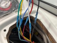
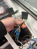
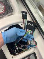
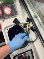
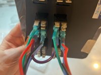
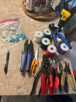
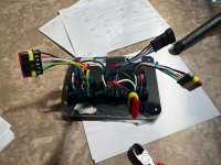
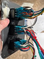
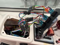
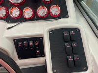
New Panel Time! (Ordered) PLUS! Bonus Relays?!


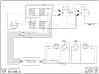
the plot thickens. There is only 1 RD/PR on the wiring diagram. Not 2.
Knowing they are connected elsewhere, I'm wondering if they wired #2 for the second switch, even though it's rather pointless to do it that way.

the Red wire (not on diagram) lets you move the drives down, but not up. However the way formula wired it, negates this, and powers the upside anyway... on the trailer switch. It doesn't seem conditional.

HOW can Green/White come from BOTH switches? How does the unit know which drive I want to go down?!
 
Last edited:

if I recall correctly, and should have video'd before I took stuff apart.
The trailer always lets you go down, but UP doesn't work until the trim limit's kick in (while in run?), but up/down both work Ignition off.?

so maybe the RD/PR IS powered, but only once the trim limits kick in.

I'll have to test that. Not sure why there are 2 wires, diagram only has 1...
if there was 1, this would make a lot more sense. (like wiring diagram shows).

sorry for rambling, maybe someone else has this same box and won't have to play detective.

with putting connectors between these wires and the switches, if I can put 3 wires in one (pin) on the boat side, I don't have to pointlessly carry 3 wires through the connector.
 
Last edited:
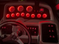
did some testing. The RD/PR wires seem to always have connectivity. (between them) Drives up or down. Maybe they only break connectivity if the drives are too far apart? then you couldn't raise either drive. Crud. the ONE scenario I didn't test, is the one the box is designed to prevent.

I can only assume this is the functionality. Because in that scenario, the power in/out doesn't matter. it just cuts the connection.

I really don't want to test this scenario, as with the tie-bar and external steering, something might give, and that could be, less than ideal.

I did manage to get the drives fairly out of level, and noticed pushing down on a single drive switch, would lower BOTH drives, until they went below the 'limit' switch, you let off the switch, then you magically regain control of just a single drive with the same switch - kinda neat.

I guess in my normal days of boating I just never mangled the drive levels bad enough to discover this functionality.

While I really want to just tie these 3 wires together on the boat side, to pass a single connection to the panel, looks like I'll tie 2 of them, and pass 2 power lines to the trailer assembly. for power in.

There will be a 6 pin connector on the trailer 'section' of the panel.
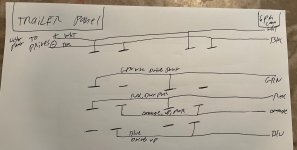
3 power in - Drives Down, Drives Up, Panel Lights
1 ground wire (Panel lights)
2 power out - Drives Down, Drives Up.

Connectors come tomorrow, hold your breath for more pics!
Glad we got that sorted! Now I can sleep soundly :)
 
Yeah, I had to give up on deciphering some of it. Long as I wire it, how it was, everything should work the same. The switches are the same, electrically.
 
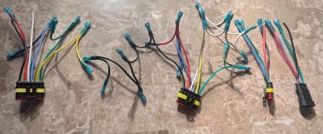
I got 2/3 of the 6 pin connectors on, and came to the realization that the drives need a 7 pin.
So I ordered some 4 pin connectors. (Gonna use 2x4 pin).
So, waiting on parts.
Dog for scale. He's goofy.

the connectors are about the quality I expected at the price point. this should work out well I think. some of them were damaged/pinched in shipping, but I ordered 6 with the plan to use only 3 anyway. they are usable, just not flawless condition.

I hope to get the remaining boat side on by the weekend. Then it's just waiting on the new panel, wiring that up, then putting the opposite connectors on that side. then snap snap snap snap, test it out, put in 4 screws, and brisk 7 month wait until LAUNCH DAY.

Ohh, if you don't have one of these:

buy one. NOW. you can strip the ends of wires so fast it's fun.
you slide it in, squeeze and DONE. pops the end right off.

the wire length the connectors will add will make this a lot easier. Plus allow me to work on the boat side and switch side separately.

I think I'll name my next boat "Waiting on Parts".

the dog is Phantom, and he's a complete chump. dog2.jpegdog1.jpegbutts1.jpeg2Conns.jpeg
 
Last edited:
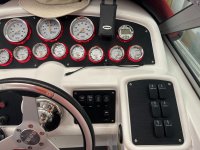
Use to use similar strippers wiring naval weapon systems, great tool. They use dies to cut the wire and not just a sharp edges so they don't cut a strain of the wire
 
4 pins arrived today.

plugs2.jpegplugs1.jpeg

NewWire says they are templating my old panel, and should have a proof to me "soon".

I put a M on the boat for one, and F for the other, hopefully no genius plugs them into each other. I did that so you can't mix them up when connecting to panel.

Once I get the panel, the fun really starts. Wiring that up, and putting the opposing connectors on it. At least this should make the whole thing a lot more modular and easy to work on. Plus I needed the extra 8" or so of wire. Without it, I don't know if any of these would have reached/worked.
 
I sure hope this all works!
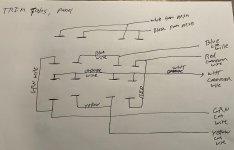
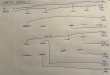
TrailerPanel.jpegTrimTabsPanel.jpegDrivePanel.jpeg

I think I spent at least $80 on wire just so I could make it color correct, and not have a panel with 50+ connections with... ALL RED wires!?!

I'm sure sometime in 20 years, all these wire colors will come in handy, right?

Just checked amazon. Yep. 8 colors ordered.

Also, all the connections are looking at the rear of the switches, so left/right are swapped, when you spin the panel around to install it.

I'm still unclear as to HOW this stupid mercury trim box actually DOES anything. it has no attachment to trim level sensors, so all it knows is:
1. Power from Ignition (OFF) (But still hot)
2. power from Ignition (ON) (Run): (#1 off)
3. Each drive Trim Limit switch (Open/close). and which is which.

So, really all it COULD do is cloneable by a basic group of relays. There is no logic or smarts or compute. It's as basic as it gets, and seems to only exist to make installing things more difficult, as any modern system would know 100x more about sensors, and be SO much easier to install.

All this can/could do is force the drives to both move or have 1 not move if over trim limit is switched. It doesn't keep them 'in sync' it just limits them from moving more than zero to trim limit switch apart. Because of the tie bar attached at ends of the drives.

Although, I do think it does something more too:

Ignition OFF: Trailer switches works up & down.
Ignition ON: Trailer switches are OFF, unless... the drives have been trimmed up to the limit switches, then you can use trailer to continue going up. (I don't think you can go down, with ignition on)

So, that's something. By separating the powered circuits of up/down on trailer switches and drive switches, you can control when they can be used... fancy for 2001 I guess.

Can't wait to dig into our live-aboard boat's systems! lol
 
Last edited:
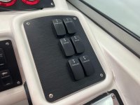
Could have a better idea of what/how it's doing and working if the actual switch inner connections are displayed. As you saw just put it back how it was and move forward
 
I know, I know... but it bugs me. I HAVE to know how it works. I was the kid who took EVERYTHING apart. and luckily over the years, more and more of those things actually went back together, with fewer and fewer left over parts ;)

Today I'd loop in the position sensors, slap together an Arduino and you could run code to actually do useful things.
 
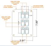
1699976449666.png1699976457419.png

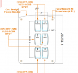
I love how they mix formats. Is it 7 and 15/16 or is it 7.9375?! USE METRIC! The ENTIRE world does.

anyway, the new panel is slightly larger and since I sent in my original, hopefully they get the screw holes correctly positioned.

Hopefully I'll have the new panel week of 20th?
 
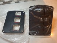
Got my latest panel. It's a dead perfect match for the screw holes. I probably should have checked a few more areas, but I was able to mount it just fine.


wireFest.jpegnewpanel2.jpegdrives2.jpegdrives.jpegpanel1.jpeg

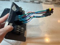
Started doing the panel side wiring, and discovered Amazon sent me red, not orange wire. Orange should be here tomorrow now. I wired everything that wasn't orange. I could have easily finished and just used red or any of the other colors, but I wanted orange! Since that's the color boat side.

Managed to burn my thumb and arm by moving from one connector to another, and whoops STILL HOT. The good news is you can twist wire easier when you have a blister on your thumb and no feeling in it...
 
Snapped everything in place to test.
Seems my wiring is pretty good.

The good news: Trailer switches and trim tabs seem to work correctly.
Tabs work fine, etc.
Trailer switches allow up/down full range and when the drive switches hit the up limit, trailer lets me continue moving them. (Trailer switches can only move both at same time).

I say switches, but the way they are wired, it's just duplicated. so it's really "one" trailer switch

Now the other news:
When using the thumb (2) switches, and/OR the dash switches:
Port/Strb move UP individually. (Seems normal).

BUT, thumb, and/or dash, BOTH drives move when pressing down.

So here's the rub.
I honestly don't recall if that's how it was before I took the dash apart.
With a stepped hull, it's rare I have to give it much trim, and if I do, I'm pushing both at the same time UP, or both at the same time for DOWN.

Or to go shallow, I'm moving both up at the same time. (and down).

There is almost zero time I think I'd push a single drive up/down, unless it was not in step with the other.
And, in several years of owning this boat, I could SWEAR this behavior was maybe 'normal'. and that It's always done this, but now I'm like 70% sure maybe I missed something?

The wiring diagram from Formula is actually wrong.
Maybe I'll fix that then start from there.

There is zero info on the internet about the "Mercury Outdrive Control Box". It's over 20 years old and seems very rare.

I'll see if I can get a pic or part number on the device it's self, maybe find more information.

So. If it's 'normal' or how it's always worked, them I'm golden, some zipties and 4 small screws from calling it done.

if it's not normal, then it seems like it would be a ton of work to redo?

I should have tested everything with video before I started, but I thought I knew my boat. You'd think you could individually move drives down, but now I just don't recall if that was possible... ugh.

Anyone know about this stupid Mercury Outdrive Control Box?!

panel3.jpegpanel2.jpegpanel1.jpeg

I'll get the "all done" photo with the backlit switches once I know things work.
 
Last edited:
After agonizing over this for a while, then not for a while, then again.

Tomorrow when I have time I'll test for continuity between Port/Strb DOWN wiring on the panel side. then on the boat side. Maybe there is a short between them. If there is - then I'll check the thumb rocker wiring. If there isn't - then it's intentional.

I'm about 80% sure I've tried to put a single drive down and noticed the other side gauge drop down a hair, but that might just confirm this short existed for a long time now.
 
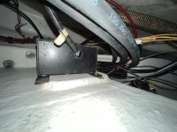
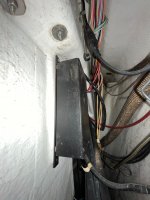
Stupid metaphorical Black Box is literal Block Box.

Couldn't find any numbers/names/labels/etc on this. there's a tag on the wiring loom, but I'm not sure I can reach it.
box2.jpegbox1.jpeg

because it's such a generic black box, even google shows me 100s of black boxes, everything from Ford Power Steering to HVAC stuff.

It looks like the cover comes right off, if it was out of the boat, but that would be a significant effort.
There are 10 wires in, 8 out, and not a single negative/ground.

The 2 additional 'in' are: Hot (battery on) and Hot2 - ignition ON.

To be frank, I'm not sure this box does anything?
 
Last edited:
Ohh snap. Found it.

Merc Part: 90362A3

Mercury Marine Quicksilver Dual Trim Kit 90362A3​


INTERNAL POWER STEERING WITH INTERNAL AND EXTERNAL TIE BAR
As a boat moves into the moderate performance range of 60-70 MPH or for a reduction in
steering backlash, an external tie bar should be added. External tie bars are usually de-
signed to attach at the aft power trim cylinder bosses. This location is an excellent choice
because of its proximity to the propeller. HOWEVER, because of the potential overstress
that can occur if one drive is trimmed much differently than the other, a dual trim control kit
(Part Number 90362A3) should be installed to limit this potential tilt differential to about 20°.
IMPORTANT: Mercury Marine does not recommend the use of an external tie bar
ONLY with no internal tie bar when using the internal power steering system. This can
cause excessive loads on the steering components on the drive connected to the in-
ternal power steering system. These increased loads can damage the steering com-
ponents, resulting in increased play in the steering of the boat.

I'm thinking, because it only knows if a drive has reached trim limit (21.75"), that the drive at tilt, cannot go up any more (it opens the circuit that powers the up circuit).

So, we know what it claims it does. But not all that it does or how it does it, or if this 'on down press' behavior is normal.
 
Last edited:
thanks, yep.

I checked for continuity between the drive down wires and found it. So I cut the wire to the thumb switches. and continuity still existed. I then tried just the thumb switch that was not cut and found it still lowered both drives. Best I can tell, this behavior is 'normal' for this device.

some final shots. Boat's covered and it's 179 brisk days until Launch 2024

done4.jpegdone3.jpegdone2.jpegdon1.jpeg

Switches still feel weird to me, I have significant muscle memory for the old rockers.

I'm sure these will feel better in a few uses.
I wasn't originally going to have them light up, but I'm glad I did.

Fall 2024 might be the other 3 panels Plus having Livorsi refurb my gauges.

Thanks all!
 
Looks great
Bit late but have you thought about water pressure gauges? Wonder if there is enough room beside the switches
 
Back
Top