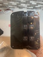
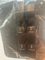
New Panel Time! (Ordered) PLUS! Bonus Relays?!


SabrToothSqrl

Well-known member
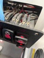
Long story short: 20 year old hard to find, expensive switches broke. Time for a new panel/switches.
So, the plan is to just 1by1 cut the wires over to the switches, but hey, I wouldn't be me if I didn't dig a bit deeper.
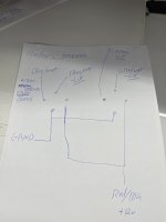
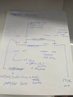
After a careful analysis, found some cool stuff, the trailer switches have 2 power supplies that determine if the drives can move/up down, on separate circuits.... spiffy.

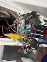
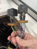
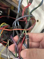
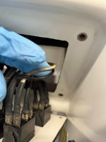
But, what has me here now, is... there are 2 relays behind 2 diodes each. If either 'drive' switch is moved up/down, it hits this relay, and from what I can surmise, sends 12v... no where... since someone (not me) CUT THE WIRES.

So, as of now, they appear to be dead weight with a lot of extra wires.

Does anyone know what these 'used-ta-do'?

I'm fine cutting them all out, as all the switches worked as expected for the 3-4 years I've had the boat now. Just seems really odd.

The add on drive trim wires for the switches on the throttle were clearly installed by a 2 year old. I'll fix that up too while in here.

thanks!

NewWireMarine is doing my panel. No affiliation, but they were nice on the phone.

Panel + 6 switches = $400ish. 5 week lead time.
New Panel.jpgdrive_Switches.jpgrelays-1.jpgdiodes.jpgcut_wires.jpgrelays.jpgdrives.jpg
 
Hard to understand without being there but guess this was part of the Merc equal trim setup. There is a Merc only module that was to keep trim levels about the same
 
I have the merc trim module, I think it keeps the trims within some angle of each other. So yeah, about the same by stopping the one you're moving if the other is too far away. It's bolted to the boat, with lots of wires to/from. I'd assume it's still wired. There is a more advanced one that actually clones 1 drive to the rest. 1,2,3,4, etc. You just trim 1, and the computer syncs them.
Can't wait for a newer boat with ALL THE TECH.

I can move either drive up/down all the way (through the drive range), without them stopping. (But only up to the drive limit), after which you'd have to use the trailer switches.

The trailer switches are wired together, so either does both. so unless you really tried to force it, they should stay fairly close to each other. And that wiring is all 2001 factory.

I debated going to a single trailer switch, as that's how it works anyway, but left it as 2, since that's how it came.

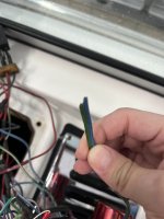
Just seems odd they cut it here. Maybe those leads did go to that. I'll look for the other end of the cut wire when I get a chance.

You'd think if you were going to the hassle of cutting that wire, you'd remove the other 8 wires and 6 connectors! not to mention the relays and diodes just flopping around in the hull. Lazy people I guess.
 
Ohh snap. looks like you called it!
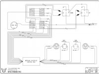
there are the diodes and relays on this file.

Mercury Trim Box.jpg


The plot thickens...

Ok, so the blue/white and green/white wires EXIT, top right of page 28 here. But then where do they go TO?! why go through this hassle of all these diodes and wires to not connect to something?!
 
Last edited:
So, the setup of relays and diodes is for when you'd use a single rocker switch to move both drives through the 'drive' range..?

I wonder if the factory throttles had a single rocker that did both?

Mine, I think, were added by previous owner.
There are 2 rockers near my thumb on the port throttle lever.
(I can move either drive, both ways). But almost never use these switches.

and some VERY sloppy wiring to/from them.

Maybe they cut this wire when they wired the new levers up? Heck, they bypassed the Neutral Safety Switch AND engine alarms.
(I fixed both long ago).

I'd have been happier with a single up/down that did both, assuming they stay in alignment.

Ohh Double Snap!
Am I thinking of this backwards?
That the top right of the diagram is power IN?

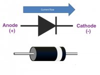
According to my diode research, the white line end means power can flow towards that end. so, yeah, I think I was looking at this backwards. The relays are powered, I don't know when, I'd have to grab my multi meter. At least I can use the ground for the ground of the new switches - I got backlit ones! They will match the rest of my switches and light on/off the same.


thanks! I think we cracked the code!

there are also errors on the wiring diagram for the down relay.
they mixed 2 of the wire colors.
 
I've searched for photos of 292s throttle levers, but it's hard to find such a small detail.
I found a video of another 292 with a single rocker on the throttle. I'm about 90% sure this is how/why it's wired this way.

I'll most likely remove the setup, as my throttles have dual rockers.

thanks again!
 
Yep!. Now the fuse thing makes more sense too. There's a power IN to the throttle rockers, that's factory, but goes to not-factory wiring. Now that part also makes more sense and 100% confirms how they hacked it in

And, since my new panel is a brisk 5 weeks away, I of course put the cover back on my boat, and hung the ladder on the wall. For the 3rd time since I started this. Maybe tomorrow will be the day I'm 'done' for 'now'.
lol
 
GOOD NEWS EVERYONE
The panel is coming sooner than expected.

Does anyone know what gauge wire formula used behind these switches? Specifically on the 'panel lights' routes.
Looks about 14 to me? it's 3mm on the outside jacket.

Looks liked they used white and black, so I'll continue that instead of randomly picking colors, like so many people seem to do ;).

I'll have to wire up the 6 new to be fed power from the panel lights, so they light up at night (P I M P). The rest I'll just swap to these style of connectors and clean up the remaining. I found 2 grounds that were 'unused'.


wires2.jpegwires1.jpeg

Also, you can run wire to multiple switches, as a SINGLE piece of wire.
I never saw that before. I'll copy that method for the lighting power wires.

anyway, I'll pickup white and black wires, marine, just need to figure out the gauge. It's amazon, so I guess I can order 12 & 14, and free returns...
 
according to this:

the wire I'm looking at to buy 16 AWG is about 3.2mm outside diameter, and they don't sell 14. and 12 seems like overkill for 6 tiny LEDs. so gonna try the 16!
 
Haven't tried anything yet. technically they all still work, I just hate seeing all that corrosion. I also don't want anything to stain the floor, carpet, etc though

Panel, wires, strippers, (not the fun kind, the wire kind) arrive Friday.

I should have some time Saturday or next week to get things in order. Not gonna rush it, I have 197 days until it hits the water, gonna do it right!
 
NEW Panel came!
That's the good news.
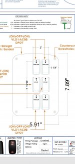
The bad news? It doesn't fit the screw locations in my dash.
VERY glad I test fit the panel before doing the wiring

Could I remove a bit of material from the panel, and make it work with washers/longer screws? Yes.

For $400 should I have to? No.

So, the good news is, New Wire Marine was very pleasant to deal with, and said they'd make it right, so I'm going to ship in my current panel for them to copy. So, good on them
The new panel looks damn good, just the screw holes are like 2-3mm off each
NewPanel1.jpegNewPanel2.jpeg
 
It's more than likely overkill, but has anyone wired in some connectors to make the panels easier to install/remove?
There are 17 'boat' connections.

2 pins for panel lights
5 pins for trim tabs
6 for drives (or 2 and a 4)
4 for trailer (or 2 + 2)

I could grab some connector kits, wire the entire panel up, nice and neat with a 2,6,6, and 4 pin connectors, then add connectors boat side, and literally snap the 4 connectors to each other, and screw the panel in place. ta-da! I'd get a bit more wire length to move stuff, and be able to do all the wiring panel side much easier.

Formula didn't do this, but to me it makes a lot of sense to do, but really I just need another 10 years out of this thing, and do not expect to be ever changing this wiring really... But can't seem to shake the idea of wiring up something like this:


would any of y'all do this?

This would tick off my color coordination plans, but make things fairly easy...

 
the factory wires are a bit short for my taste, and the weight of the wiring seems to be almost on the factory switches - which was fine as they were o-ring terminals and screwed in place... I think for $11 I'll see if they are up to my standards of quality. If they are, I'll use them, if not, I'll skip it.
it should make the wires about 10" longer (unless I trim), and make the actual install easier too.. which is why I think I keep coming back to the idea.

I'm thinking about doing my other panels, and if they were in place man that would be a fast swap. but you are correct - assuming it's wired correctly and working - there should really be no need to change anything in here.

thanks! hopefully they get me the updated panel back. 1-2 weeks.

I'll play with the connectors and heatshrink in the mean time. I've done 100s of these connections, but I've never wanted a panel to be more perfect than I want my boat panels.
 
Started to dig more into the wiring, and hoping to do the 'boat' side of the connectors this week while waiting for the newer panel.

There are many, MANY wires coming from the "Mercury Outdrive Control Box"
2 of which are, according to my eyes, Orange/Purple, but labeled Red/Purple from the box/boat.

I assumed these were 'power in' to the switches, since they were connected to the power in of the switch (one to each side, DPDT).

However, they don't seem to have power, while a red wire that is OEM, is connected to the same post as one of these.
Between the Red/Purples wires is continuity. (connects to box)
While the red wire comes from 'elsewhere', but is OEM. It lives alongside a Purple wire that appears to have powered the 'trim' switches.

This Mercury Outdrive Control Box wiring is VERY.. well.. stupid. There are multiples of the SAME wire in the bundle. Multiple Green with white stripe.

I removed the wires from the trailer, thinking there would be 4 wires. 2 power in, 2 out. But nope. there's that extra red one.

I wonder if it uses that to sense when move both drives, or just one?

How can there be 3 of the Green with white stripe in the SAME bundle?!
How would the gizmo know if I want both drives down, a single drive down, or what?! also 3 of the blue wire! All blue! is it port? strb? WHO KNOWS! It's BLUE

Even the wiring diagram shows 3 wires with green/white stripe! How does this work?! Does it even work?!

**shakes wire strippers at sky**

wait. does the box know what I want when applying 12v to a random blue wire, based on something else? Based on 'where' the 12v is coming 'from'? there has to be some conditional state here, otherwise it's always the same. So what's changing? what else does this box know? the box 'knows' the ignition position (off/run).

it knows trim limit (off/on).

SabrToothSqrl - Electrical Detective!
 
Last edited:
Back
Top